How-to-build-a-630m-antenna
Cet article pour vous motiver à venir rejoindre les passionnés de 630m..."Tant va l'antenne, tant va la station disaient nos anciens...." cet adage est toujours d'actualité , merci à Nick VK2DX d'y avoir pensé et de nous faire partager son expérience! ( pour plus d'infos: f6ciu@yahoo.com & twitter.com/f6ciu )
Introduction.
While there are many websites which will provide plenty of information to an enthusiastic 630m antenna builder, there is a real 'danger' that such a project may be taken too lightly or executed in the 'wrong order'.
For example - realizing that the ground system is not adequate at the point
when one's already trying to adjust resonance and impedance while the antenna structure is collapsing
may be a challenge even for an experienced antenna builder.
Inevitably, without a clear understanding of the building steps, the end result will be failure and disappointment,
not to mention wasted material and time.
On the contrary, with a bit of planning, such a project will be lots of fun and
the end result will be a 'decent signal' and plenty of on-air fun,
even from a small city lot.
Below is a DRAFT for an article on this subject.
Please read, improve, comment and fix/edit.
Once the article is finalized, it will be saved as a .pdf and uploaded to the group file.
As you can see, I am brave enough to demonstrate that I am not an expert in this area
however it is now up to you to turn it into something meaningful
and useful to potential antenna builders.
Draft
This article is not a definite "how-to-build-a-630m-antenna" tutorial.
Rather it is a quick guide outlining some important practical steps which
will allow you to get on air while avoiding disappointment.
It is aimed at short-wave amateur operators who live in urban area and are in general
not familiar with practical aspects of erecting and tuning a short "inverted L" antenna
for a medium wave band.
The build is divided into six practical steps. For the project to be a success, each step should be taken seriously.
The key phrase is: take your time!
SAFETY first: the radiating structure described here is relatively tall (10-15m).
If you have power lines within a radius of 20m or less of the intended placement of antenna,
then this project is unfortunately NOT for you. (You can still enjoy 630m on the receiving side!).
Another word of warning:
erecting a tall structure in an urban backyard will inevitably have visual and social impact.
In most cases, such impact is negative and antagonistic.
Be aware that your neighbors and family members will most likely express their disapproval.
It is therefore important that you do your best to avoid any conduct which will further
antagonize your loved ones: stay focused, well organized and keep the backyard and lawn clean!
Here are the 6 practical building blocks of your new 630m antenna:
- feed line
- ground system
- radiating structure
- loading coil
- variometer / tuning unit
- impedance matching transformer
Step 1.
Once you have determined a suitable antenna spot in your backyard, provide a length of feed line
to that point. Here is the good news: practically any 50 ohm co-axial cable which you already use on HF
'will do' on MF. Starting with a "fresh" piece of cable is always a good idea, especially with a new antenna project. If possible, bury the cable in the ground or at least hide it.
Feed it into your shack in the least conspicuous way possible: running a cable underneath the kitchen table and through the bedroom will definitely kill your 630m project before you even start transmitting!
If you are drilling the cable through a brick wall, make sure to seal the brickwork. Solder connectors. Plan to spend a whole day (or more if necessary!) working on your feed line.
You will know you've done a good job if no one notices it!
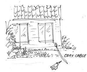
[coax, connectors, shawl, drill with masonry drill bits, soldering iron etc]
Step 2.
In short, the more wire on or under ground, the better. If you are an HF operator, forget about
resonance of radials - anything you install will be way too short anyway. Unlike your perfect feed line,
the ground system is a compromise which will fall short of ideal, or even optimal, for MF.
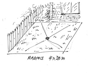
However, the very starting point is installation of at least 4 symmetrical wires (radials) positioned in each direction.
If possible, aim for lengths of around 20m. Install many more if you can! Like in step 1, bury the wire underneath the lawn. Aim for a straight stretch, but zig-zag if you have no other option.
From an electrical point, the wire diameter is not critical but for practical reasons use an insulated copper wire
of 2mm diameter. Ground system made of thinner wire will disintegrate fairly quickly.
Later on, you will add more radials. Again, while more shorter radials is better than fewer long ones,
you could have a hard time tuning the short vertical antenna without at least 4 x 20m radials.
Make sure to install cable ring terminals at the end of each wire. Attach them (screw) to a small copper plate
at the proposed antenna base, close to the co-ax cable. Don't forget to pre-drill more holes in a copper plate for further radials.
Again, your ground system should be invisible, hidden or completely under the lawn.
Time frame: a day's work!
[wire, copper plate, ring cable terminals, screws, drill, soldering iron, shawl (again!) etc]
Step 3.
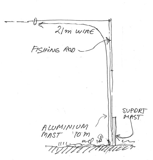
In this step you will be erecting a structure which will support
the antenna wire. Cut about 21m of wire - this is the amount of wire you want 'up' in the air.
The simplest 'structure' to erect would consists of aluminum tubing and fiberglass fishing rod.
The first 13-14m of wire would go vertically, along the structure, and the remaining length is stretched horizontally.
There are a couple of important points here to be aware of:
- keep the 'vertical' section lightweight and as high as practically possible. 10m
is the bare minimum, and 15m or more would require serious mechanical engineering, guy wires,
and most likely a building/construction permit.
An aluminum tubing mast of 10m extended to 13-15m with a fiberglass fishing rod may be
a good compromise between weight and a self-supporting sustainable height.
- the horizontal part of the antenna wire should not slope down under a sharp angle.
Instead, it should be stretched parallel to the ground. You may need a second
high support point (a tree or another fishing rod).
- if your vertical is extended with a fiberglass fishing rod, the top loading wire should be a light and
multi-stranded conductor. Otherwise it will come down with the first wind.
- when erecting the vertical, arrange to have a helper who will keep the
wire away during the take-off phase. Having to take the vertical down just to untangle the wire is
very frustrating and time consuming.
- the light-weight vertical structure may not require more than one set of guy wires.
Or even no guy wires at all - if you attach it to a short but sturdy support mast/stake.
Such support pipe must be well insulated too. Use a porcelain base insulator.
Once you have the wire up in the air, attach the center of the feed line to the vertical section, and the shield to the radial system.
If you have an antenna analyzer - like MFJ or similar, find the resonant frequency.
The exact frequency is not that important, but the antenna should be resonant somewhere in the 80m band.
This step is the most challenging. Plan well ahead, have a helper or two.
Mechanically, the supporting structure must be well designed and engineered.
[wire, aluminum telescoping tubing, one or two fishing pole / fiberglass rods,
ceramic insulators for both base and wire, rope, guy rope, tools (too many to list!) etc]
If you are starting form scratch, be prepared to spend at least on day on antenna 'structure'.
Step 4.
In this step you will build a large loading coil. The purpose of the coil is to bring the resonance of
the antenna as close to 475 KHz as possible. A simple loading coil with a modest Q-factor will be sufficient
to get you on air. Of course, you may build a 'better' (larger!) one later.
For a former, use plastic / pvc bucket approx 30cm in diameter.
Wind around 60 turns with of 2.5mm yellow/green 'earth wire' (inductance of around 600uH).
Make sure that the coil is mechanically sound. Allow a couple of hours for a good job.
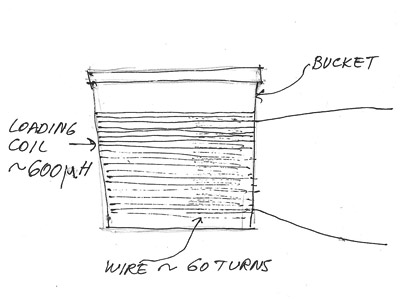
[wire, bucket, cable tie, ring cable terminals]
Step 5.
With the loading coil inserted in series with antenna wire, you will still be 100 Khz or more away from your
desired resonance at 475 KHz. For fine tuning, you need to insert a "variable inductor"
or a variometer between the antenna wire and loading coil. Practically, a variometer consists of two coils wound on two circular formers, housed one inside the other.
The inner coil can be rotated to vary the coupling. Both coils are connected in series.
Some experimenting will be required to cover sufficient adjustment/tuning range.
To simplify mechanical construction, the smaller rotating coil can be inserted directly into
the large loading colt (built in the previous step). However you may find the tuning task a bit easier
having the stand-alone variometer. From an electrical point, either solution is equally good.The exact diameter of both forgers is not critical, as long as the smaller one
can physically rotate inside the larger.
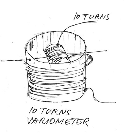
It is recommended that the adjustment range of the variometer should be 10% of the loading coil inductance,
or around 60uH in our case. Build time: 4 hours
[more wire, two forgers, ring cable terminals, more cable ties, etc]
Step 6.
A short inverted L antenna tuned to the 630m band will have unknown impedance.
The impedance at feed point will depend on many factors - ground system, antenna 'size' and location, and
nearby objects will play significant roles. Most likely it will be anything but 50 ohm so an
impedance matching transformer would be required.
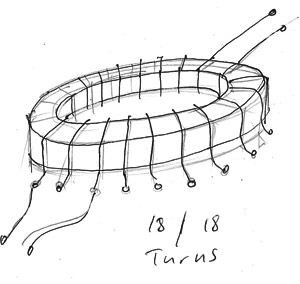
For transmitters with an output power of 100W a toroid core like FT-140-J or FT-140-43
will be sufficient. The secondary consists of 18 turns of 1mm wire.
Primary: wind 20 turns over the secondary coil and tap on each turn after the 10th. Insert the transformer in series with the loading coil and ground radial system.
Attach the co-ax as per diagram, centre conductor to turn 16 as starting point.Time required: 1 hour.
[toroid, CuL wire 1mm, ring cable terminals, etc]
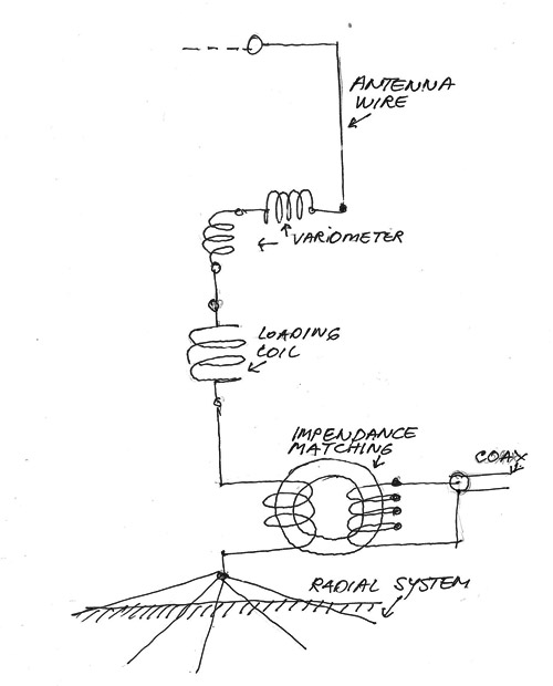
At this position, your 630m antenna is ready for tuning and final adjustment.
(to be continued....)
73, Nick VK2DX
F6CIU web design